

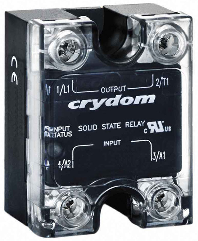
How Do Solid State Relays Work?
Posted by Morgan Spano on Oct 4th 2022
Electrical relays, in one form or another, have been around for over 100 years. It wasn’t until 1971 when Crydom invented the solid state relay that we had our next big step in relay technology.
First, let’s start off with some common vernacular we tend to see when discussing SSRs.

This may be a given, but why not start with the absolute basics? The main difference between an electrical mechanical relay and a solid state is the fact that there are no actual moving components in a SSR (just like the name suggests!) Rather than relying on a physical contact moving to complete the circuit, SSRs rely on either infra-red light emitting diodes or LED couplers to operate.
Types: Transformer, Opto-isolator, capacitor, hall effect, magnetoresistance
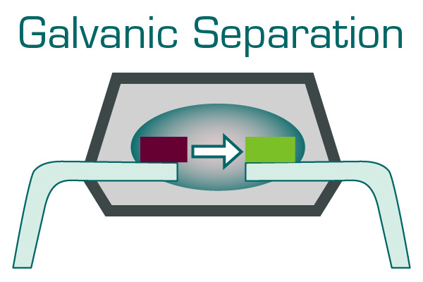
Galvanic Separation
This is the practice of keeping electrical components separated. Instead of using a physical connection to activate the relay, galvanic separation means the connection will have to be made using LED or infrared light. While ensuring no fault can occur, galvanic isolation also allows for wired communication to multiple devices that need separate power regulation.
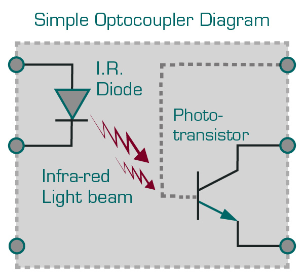
Optocoupler (aka Opto-Isolator, optical isolator or photocoupler)
In reference to SSRs, optocouplers are the light-source (commonly LED or infra-red) components that allow for switching to occur.
The transmitter (Tx) and receiver (Rx) are positioned within the SSR where they are energized by the signal control. Once energized, the optocoupler switches the circuit (either to open or closed) which allows the full voltage signal to pass through the SSRs output.
Generally speaking an optocoupler is comprised of two separate components, one for transmitting the signal and another for receiving; but is more often than not referred to as a complete unit
Signal Control (aka Control or Circuit Voltage)
A relatively low amount of voltage specifically used to switch the optocoupler from off to on, or vice versa. Generally based on the manufacturer this can be anywhere between 3 or 4 volts DC to 24 volts DC.
Switching Devices
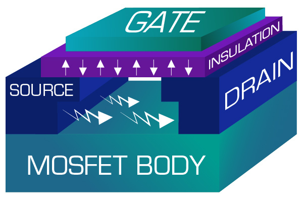
The MOSFET (metal-oxide-semiconductor field-effect transistor) is a semiconductor device comprised of two metaloxide semiconductor field effect transistors (MOSFETs), one N-type and one P-type, integrated on a single silicon chip. MOSFET is generally used for switching DC loads.
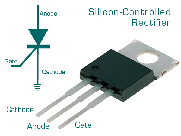
SCR The silicon-controlled rectifier (SCR):
A four-layer solid-state device that controls current flow. The SCR acts as a switch, conducting when its gate receives current, and it continues to conduct for as long as it is forward biased. The SCR is ideal for switching all types of AC loads.
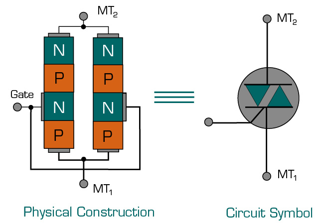
TRIAC:
A triac is an electronic component approximately equivalent to two silicon-controlled rectifiers joined in inverse parallel (paralleled but with the polarity reversed) and with their gates connected together. This results in a bidirectional electronic switch that can conduct current in either direction. The triac is ideal for switching resistive AC loads.
Cool! Now that we’ve covered some of the more common jargon found while discussing SSRs, we can begin breaking down the different types of SSRs based on their switching frequencies.
Zero Switching:
- For resistive and capacitive loads
- Upon application of the control voltage, the SSRs output is activated at the first zero crossing of the line voltage. The response time is less than 8.33 ms. Also offered with an optional system monitoring function and current sensing function
- Due to the high surge current and blocking voltage capabilities, SSRs of this switching type will also perform successfully with most inductive and capacitive loads. They are the most commonly used SSRs in plastics molding machinery, packaging machines, soldering equipment and machinery for the food processing industry.

- Instant-On Switching:
- For inductive loads.
- The SSR output is activated immediately after applying control voltage. Consequently, this relay can turn on anywhere along the AC sinusoidal voltage curve. Response times can typically be as low as 1 ms.
- The SSR is particularly suitable in application where a fast response time is desired, such as solenoids or coils.

- The peak of the inrush current could hereafter be reduced during the first half period for inductive loads. Ideally suited for inductive loads with a remnant iron core (i.e. transformers).

- For resistive and inductive loads.
- The power semiconductor in the DC switching relay operates in accordance with the control input. The response time is less than 100ms. DC switching SSRs are used with resistive and inductive loads for the control of DC motors and valves.
- When switching inductive loads it will be necessary to interconnect a freewheeling diode surplus voltage parallel to the load as protection.

Analog Switching:
- For resistive loads.
- Since the 4-20mA or 0-10VDC control input of the analog relay can be varied, the output operates in accordance with the phase control principle. The relay is equipped with a built-in synchronization circuit in order to achieve phase angle control. The output is proportional to the input signal. The transfer function is linearized and reproducible.
- These SSRs are highly advantageous in closed loop applications or where soft starting can limit high inrush currents. Ideal for use in switching quartz heaters or in applications which demand precise temperature control.

Analog Full Cycle Switching:
- For resistive loads.
- With this particular switching principle the SSR provides a number of full cycles, evenly distributed over a fixed time period, depending on the control input (either 4-20mA or 0-10VDC) – with the low value of the input corresponding to zero and the high value of the input to a full output with a period of 1.28 seconds.
- Typical applications include: analog control of heating elements with mount or automatic controllers with 4-20mA or 0-10VDC control signal. Control of heating zones, analog control of fragile heating elements which are used for cutting, welding, etc. which can have their lifetime extended due to the reduced thermal load stress.
Zero Switching with System Monitoring:
- For resistive and inductive loads.
- The system monitoring (sense) SSR provides an alarm output in the event of a circuit failure. Internal circuitry monitors:
- Line voltage
- Load current
- Correct functioning of the SSR
SSR input status:
- The relay is designed for applications where immediate fault detection is required. An alarm output signal is available to determine fault status.
- For resistive and inductive loads.
- The Solitron MIDI current sensing SSR is a zero switching type which also provides an alarm output when it senses variations in the load.
- Typical conditions that can be detected include: heater break, open circuit, partial heater short circuit, blown fuse, semiconductor short circuit and faulty power connection. Integral current sensing eliminates the need for additional external equipment.
- “TEACH-IN” set point is achieved by pushbutton or remotely where an HMI is preferred.
- As shown above, the PNP alarm output provides a series of pulses which identify the specific type of fault detected. Interfacing to a PLC can provide a clear indication of fault. An NPN alarm output is also available.

We’ve got a team of technical support agents ready to help you find the right relay for your application. Just give us a call at (847) 658-8130 and ask for tech support or email us directly at: [email protected].