

Protecting Pumps from Dry Running with LS Electric
Posted by Morgan Spano on Jan 12th 2024
Problem: Pump failure and seal loss due to dry running…
A common and potentially expensive issue experienced by many pump operators is how to avoid dry running. In any application that utilizes constant or variable torque pumps for liquid distributions, i.e. mixers, grinders, clarifiers, chemical processing or manufacturing, wastewater distribution or even water pumps for large scale buildings, maintaining fluid levels is paramount for equipment functionality.
Designed to function with a liquid acting as both coolant and lubricant, running dry can quickly run into three potential issues.
1) The impeller will melt along the shaft, causing the impeller to seize onto the shaft.
If the impeller seizes, it will stop and not rotate. To correct this, the pump should be taken apart and a drill bit should be used to clean out the bore of the impeller.
2) Damage to the rear housing may occur.
Another potential failure may be a hole developing in the rear housing, allowing liquid to escape. Or, the boss of the rear housing, which secures the pump shaft, may become deformed, which will allow the shaft to move instead of remaining stationary.
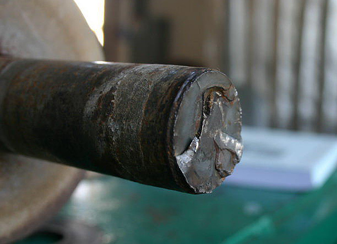
This will cause damage to the impeller and may cause the shaft to break from the impeller bouncing on it. If the pump is made from stainless steel, it is unlikely holes will develop whereas the impeller bushing will likely seize onto the shaft.
3) Dry running can also damage seals causing them to burn up and fail.
The amount of time it takes for a pump to suffer damage from running dry depends on many variables including pump size, the type of fluid used in the pump and bore size but could easily be as little as 20-30 seconds to produce irreversible damage to the system.
Human error is a common root of many dry running failures in pump applications; whether it’s leaving a pump unattended after offloading is complete or incorrectly priming the pipe system before running. These potential mistakes, in addition to general wear and tear, can make dry running a very expensive issue costing production much in down time and replacement equipment.
Solution:Preactive vs. reactive maintenance by using improved instrumentation to better monitor and manage fluid levels, hire and/or train staff to closely monitor equipment or implement a different pump system that is less sensitive to dry running conditions.
While better training operators to manage the pump system may seem like a viable option, some pumps cannot be monitored by personnel due to environmental factors.
Many factories have implemented a predictive or preventative maintenance schedule that alleviates some potential failure risks, but malfunctions still have the potential to occur at any time. Alternatively, switching to a less sensitive pump system that uses externally cooled/lubricated mechanical seals is an option but this may not always be practical in certain applications with specific requirements. “Centrifugal pumps have a specified performance window of operating curves, moving out of that window or moving too much within it may produce stresses that can result in damage to the pump” (McIntyer, Pumps&Systems).
With the multitude of factors that can degrade pumping equipment throughout the application, it is realistic to hope for the best but plan for the worst in order to minimize the potential failure.
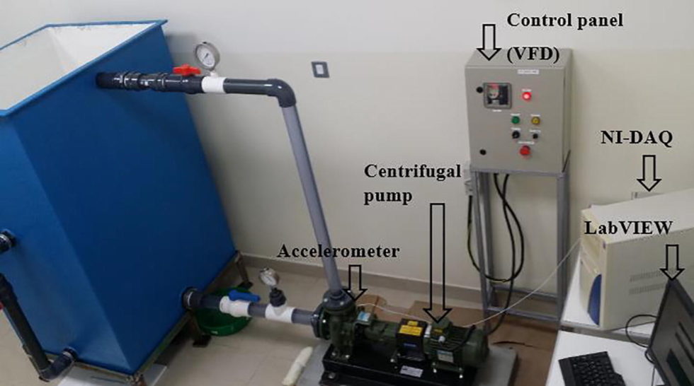
That’s where instrumentation comes into play, primarily in sensing the actual motor work load while connected to the pump. Generally this would require the installation of a sensor to monitor fluid levels, power consumption or pressure within the system. One method of determining a drop in pump pressure is to monitor the power (either kilowatt or horsepower) consumption.
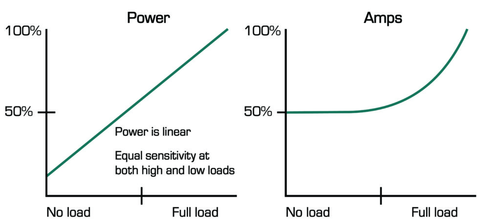
Since pumps and fans are variable torque loads, the power consumption will vary based on the frequency (speed) (LS Electric, H100 Underload Detection).
A benefit sensing horsepower has over current is the fact power is linear and will maintain a consistent sensitivity in both low and high loads.
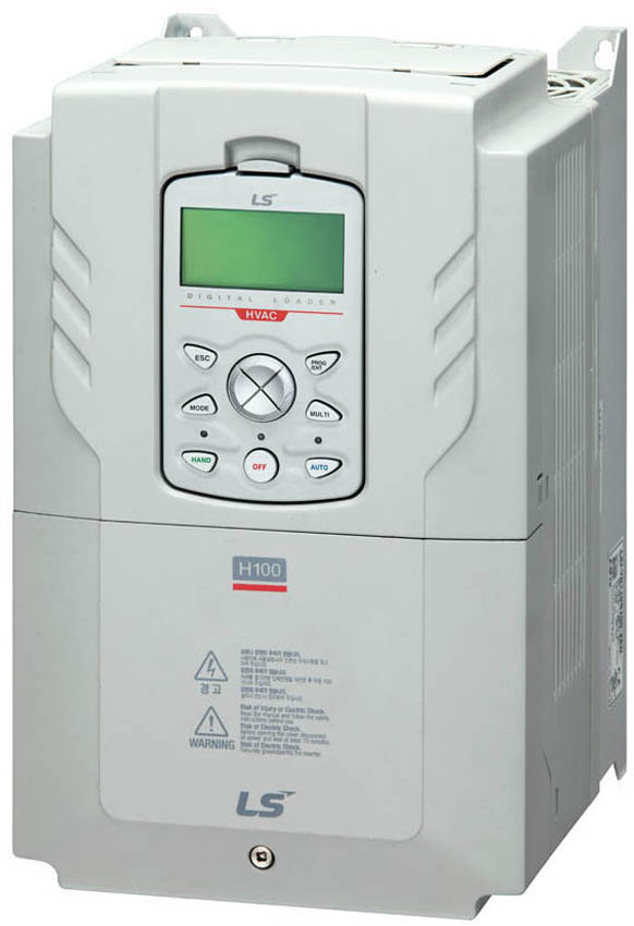
Luckily, LS Electric has come up with a built-in solution which allows for “Under Load” detection, aka dry pump protection. The included programming option is easy to implement and allows you to monitor the pumping application’s output frequency and output current or power.
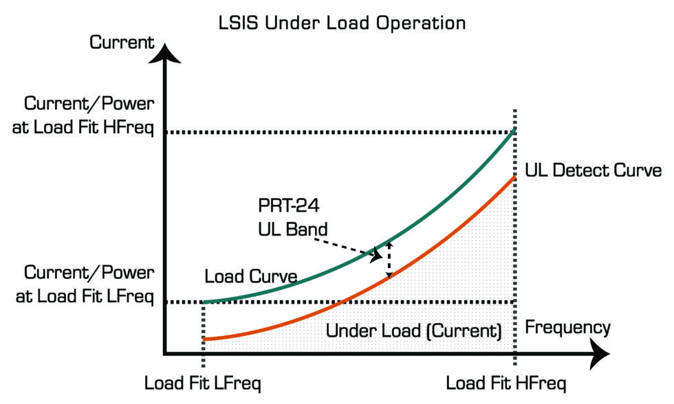
Since we are applying this to variable torque loads, it is important for the VFD to know what current or power level to expect at a given speed. If that level is low and out of the Under Load bandwidth range for a certain amount of time, the Under Load trip or warning will occur.
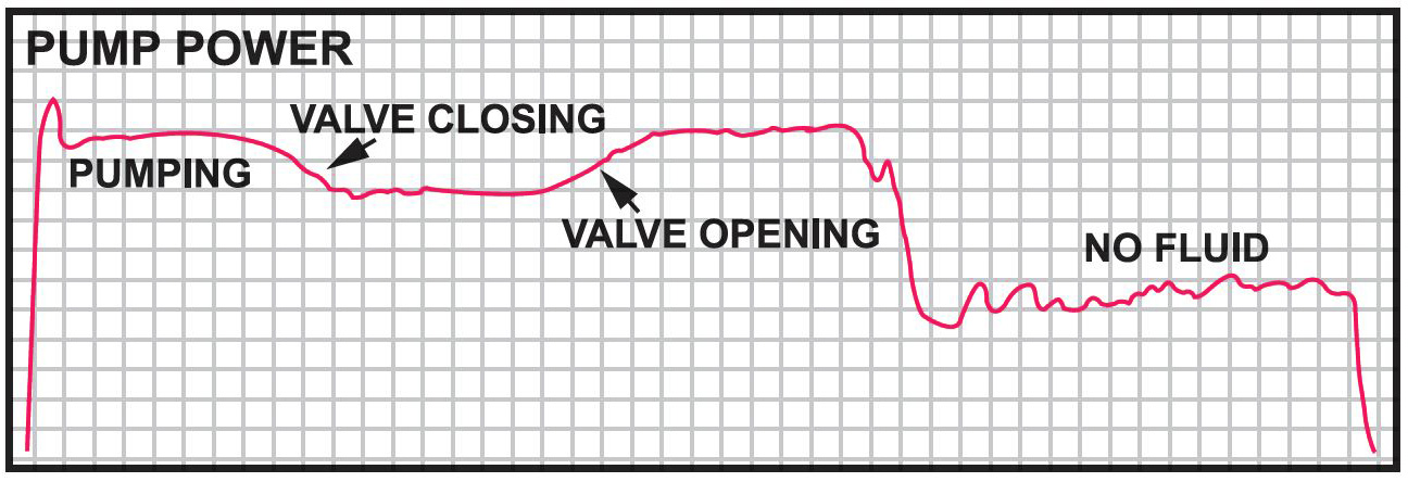
As you can see if the “Under Load Operation graph,” the H100’s Under Load protection can be utilized to trip out the VFD and protect the pump if it detects a change in power/current consumption. This same function can be used for fan applications as a belt-break detection
H100 ‘Under Load Sequence’ Programming Setup
-
Setting up Under Load detection is intuitive and easy. Follow the below steps as a guide.
-
Enable UL Warning by setting PRT25=Yes. A warning can be used an alert for an Under Load without tripping.
-
Enable UL Trip by selecting “Free-Run” or “Dec” at parameter PRT27. This selects how the motor will stop when the trip occurs.
-
The detection source for the UL Trip is set in PRT23. It can be set for current or power.
- The UL detection band is the level which will cause the UL Trip. This is set at PRT24. Note that this is a % of motor current or power (kW).Lastly is the setting of the delay times. PRT26 is the warning time delay. PRT28 is the trip time delay.
This included feature makes the H100 series VFD and excellent solution to many pumping issues encountered in the field while saving the user time and money.
Special thanks to Ron Waltz for assistance and knowledge.